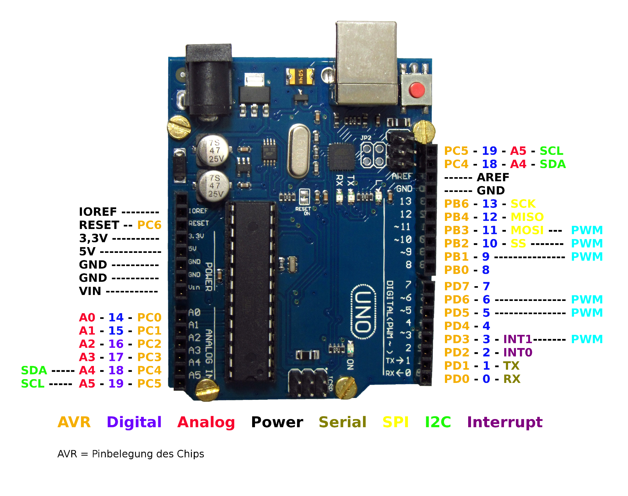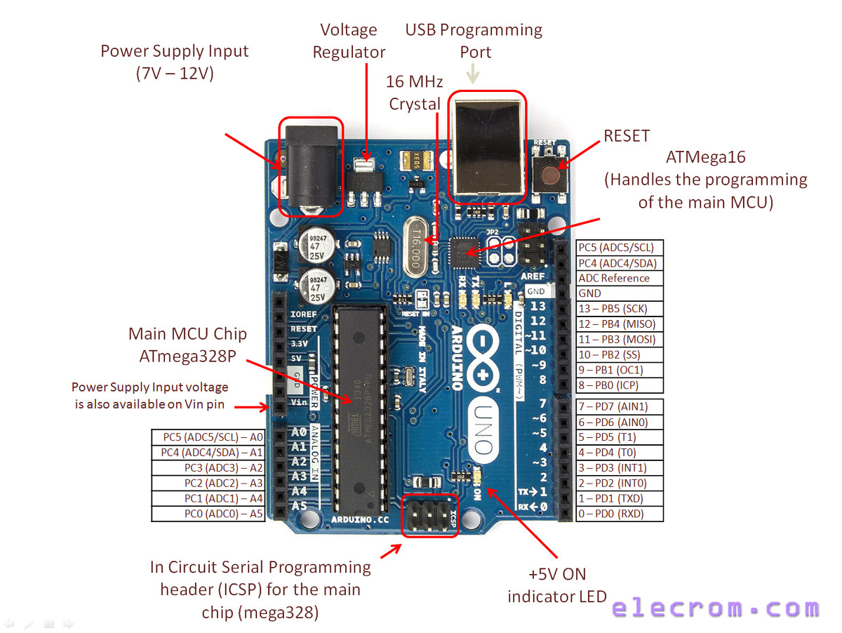
It is used to read data from specified GPIO pin. We can read data from GPIO pin using digitalRead() function. To configure pin as digital input, pinMode () function is used. Read more about board specific functionality in the Arduino Uno module documentation in the Library Reference. So, there is no need to configure pin as input. Arduino pin are set as digital input (default). To read data from senor or from any device/circuit, we need to configure digital pin as input. Pin no -+number of a pin whose mode we want to set.Į.g. This function is used to set output as HIGH (5 V) or LOW (0 V) We can set output on these pins using digitalWrite () function. These pin produce output in terms of HIGH (5 V or 3.3 V) or LOW (0 V). If any connected device to Arduino withdraw current more than 40 mA from the Arduino then it will damage the Arduino pin or IC. The most recent revision of the board exposes the 1.0 pinout on rev 3 of the Arduino UNO board. Note: While connecting devices to Arduino output pins use resistor. This Ethernet Shield allows an Arduino board to connect to the internet. These Arduino (ATmega) pins can source or sink current up to 40 mA which is sufficient to drive led, LCD display but not sufficient for motors, relays, etc. pinMode (3, OUTPUT) //set pin 3 as output Pin no- number of pin whose mode we want to set.Į.g.

This function is used to configure GPIO pin as input or output. To configure these pins, pinMode () function is used which sets the direction of pin as input or output. We have to configure these pins to use as output. Pin Configuration Digital OutputĪrduino (ATmega) digital pins can be configured as output to drive output devices. Let’s see digital input, output of Arduino (ATmega).
ARDUINO UNO PINOUT CODE
Crystal Oscillator – The Crystal oscillator has a frequency of 16MHz,It provides the basic timing and control to the board.RESET Button–It is used to reset the board button every time we flash the code to the board.Īrduino analog pins can also be used as digital input/output pins. Voltage Regulator-The voltage regulator converts the input voltage to 5V.

To provide reference voltage for input voltage.
ARDUINO UNO PINOUT SERIAL
Used to receive and transmit TTL serial data.ġ0 (SS), 11 (MOSI), 12 (MISO) and 13 (SCK) Used to provide analog input in the range of 0-5V Maximum current draw is 50mA.GND: ground pins. Vin: Input voltage to Arduino when using an external power source.5V: Regulated power supply used to power microcontroller and other components on the board.3.3V: 3.3V supply generated by on-board voltage regulator. There is a polarity protection diode connecting between the positive of the barrel jack to the VIN pin, rated at 1 Ampere.The versatility of the pinout provides many different options such as driving motors, LEDs, reading sensors and more. USB cable – when connected to the computer, provides 5 volts at 500mA. The voltage should be within the range mentioned above. VIN Pin – This pin is used to power the Arduino Uno board using an external power source. What is the voltage of the Arduino Uno Vin pin? Above 12 volts, the regulators might overheat, and below 7 volts, might not suffice. The board can be powered by 5-20 volts but the manufacturer recommends to keep it between 7-12 volts. Secondary pins are mostly communications pins such as I2C and SPI. There are pins with secondary functions as listed below. The Arduino UNO board is divided into digital pins, analog pins and power pins. What are the different types of pins in Arduino?

In the Arduino Uno pinout, you can find 5 GND pins, which are all interconnected.

In this post, we’ll go over the capabilities of the Arduino Uno pinout. Pinout diagram shows that each pin has multiple functions such as PWM, interrupts, general-purpose input-output and analog channel. The versatility of the pinout provides many different options such as driving motors, LEDs, reading sensors and more. The Arduino Uno pinout consists of 14 digital pins, 6 analog inputs, a power jack, USB connection and ICSP header.


 0 kommentar(er)
